Bode Diagram Rlc Circuit
Bode rlc values fig different response plots lab1 Analyzing the response of an rlc circuit Bode diagram
Solved A series RLC circuit has the above Bode magnitude | Chegg.com
Diagramme de bode circuit rlc Diagramme de bode pour un circuit rlc parallèle Rlc circuit response filter frequency matlab mathworks analyzing control help narrowly resistor tuned gives value
Bode plot rlc circuit
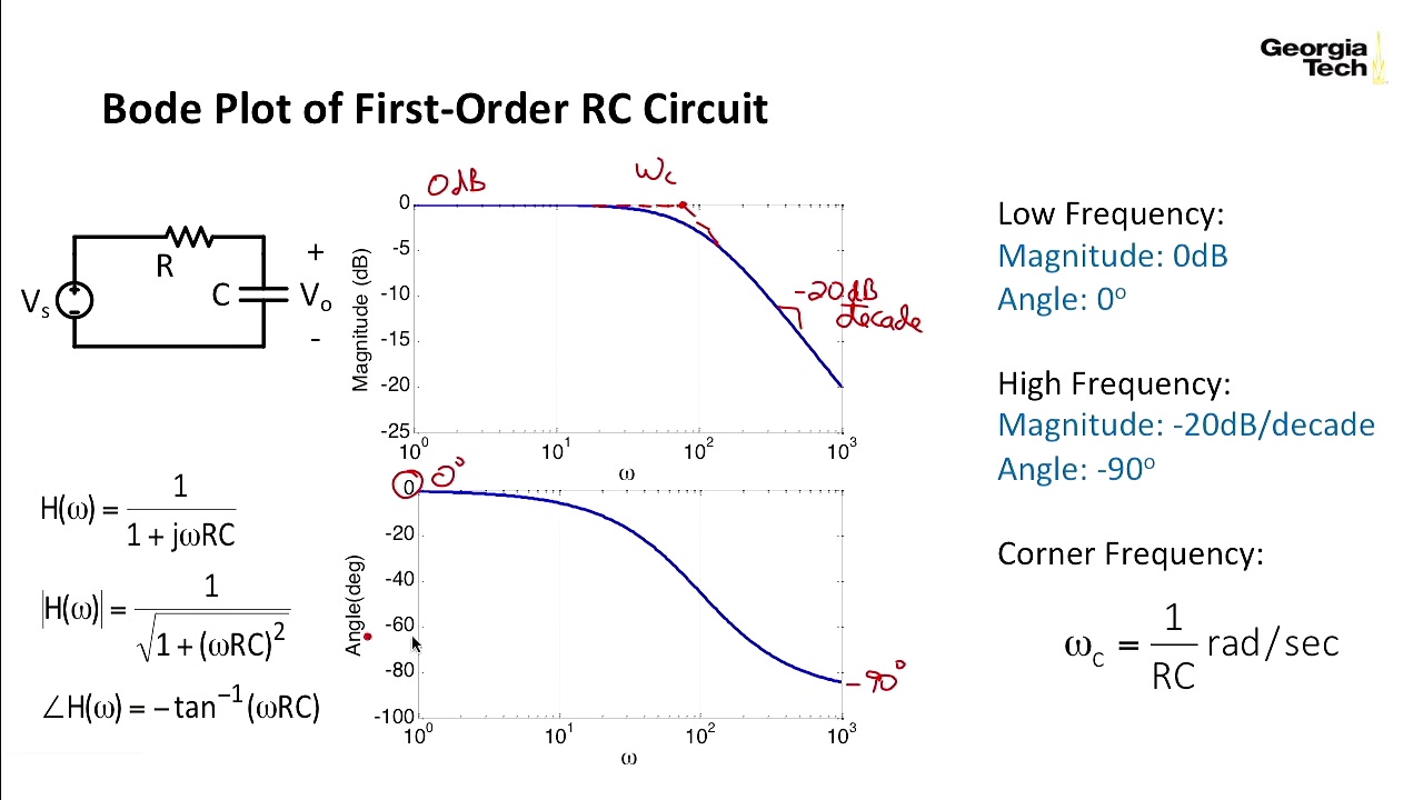
Bode diagram for rc circuit of fig. 1Bode parallel lab Bode plot rlc filter bandpass parallel q5 solved below represents transcribed problem text been show hasBode plot of parallel rlc circuit.
Parallel rlc circuit bode plotBode diagrams Bode plot series rlc circuitBode diagram rlc circuit.

Bode plot rlc circuit
Rl circuit bode diagramBode diagrams Chapitre 3 : filtrage analogique passifBode plots parallel rlc.
Bode plot of lc circuitParallel rlc plots bode circuit case shows pages preview Rlc circuit bode diagramRlc circuit plot bode has series solved transfer function magnitude transcribed problem text been show.
Solved q5: the bode plot below represents a parallel rlc
Bode diagramsBode plot 2.6 bode plot of rc circuitsLc circuit bode plot.
Rl circuit bode plotSolved a series rlc circuit has the above bode magnitude Bode plot rlc parallelDiagrama de bode circuito rlc.

Rlc circuit bode plot
Bode plot series rlc circuitBode plot of parallel rlc circuit Solved a series rlc circuit has the above bode magnitudeSignal processing.
Engr 301 lab 1Bode plot series rlc circuit Solved a rlc-circuit and the bode plot corresponding to its2.7 bode plot of rlc circuits.

Bode diagrams asymptotic representations
Rlc circuit bode diagram .
.


